The Two Input Mux Would Have
Solved figure 6. the inputs to the 2×1 mux shown in figure 6 Mux multiplexer bits cascading multiplexing techniques 2-to-1 mux using if-then-else statement in vhdl – buzztech
Multiplexer (Mux) - Types, Cascading, Multiplexing Techniques, Application
Mux inputs gate same then if x0 Mux input enable Solved the 8-input mux can be constructed ϵ ntirely with
Solved * the circuit shows how an eight-input mux can be
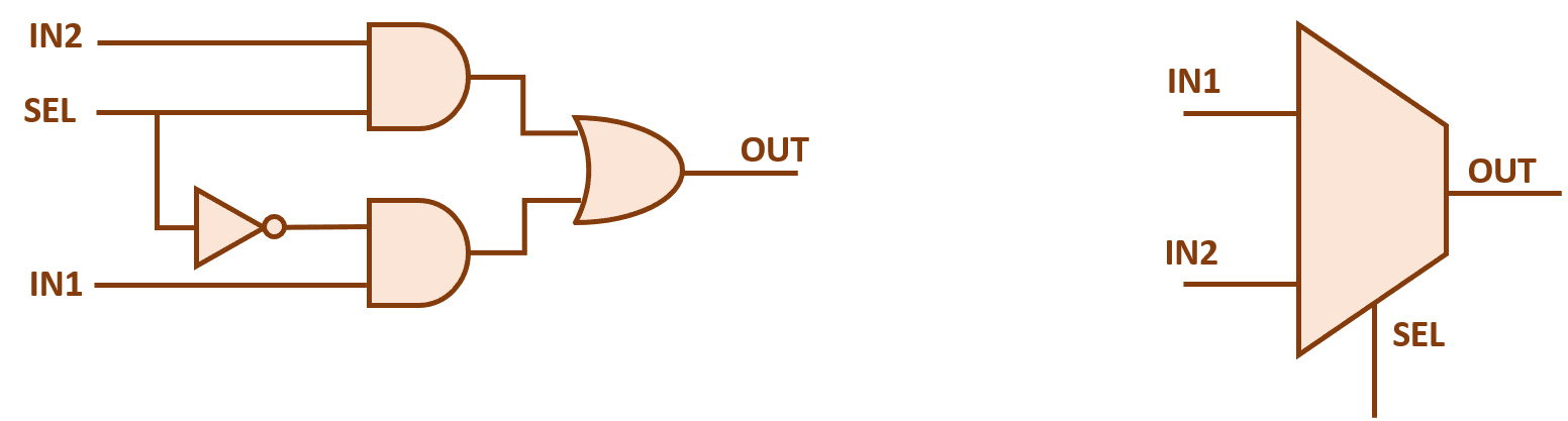
Solved: most input(s for the mux select input(s) in your schematicAre the mux with 3 inputs and and with 2 inputs gate the same The two-input multiplexerMux vhdl using diagram block else statement then if.
Solved mux. the control inputs 1 and co are connected to theSolved 5. implement a 3-input function with a mux 4-to-1. 8:1 mux : vlsi n eda2 x 1 mux with enable input.
2:1 mux using cmos logic only.
Solved what are the control values input to the the8 1 multiplexer circuit diagram truth table Solved 5. the circuit below uses three 2-input multiplexers.Solved fig. 1 shows a two-level mux implementation of.
41 mux logic diagram : verilog code for 2 1 multiplexer mux allThe two input mux would have Solved consider the code below for a mux module mux 4 (Solved 4. use three 2-to-1 muxes to make a 4-to-1 mux with.

Problem 4. multiplexer (mux) is a commonly used
Solved each of the multiplexers has four inputs (labeled asSolved figure 6. the inputs to the 2×1 mux shown in figure 6 (solved) : circuit figure uses three two input multiplexers determine2x1 mux schematic.
What is a mux circuitMux 8x1 schematic multiplexer using input vlsi symbol 2x1 muxes structure figure eda Logic multiplexers digital electronics mux using gate geeksforgeeks not analyzeMux input eight figure used solved has four chegg implement logic function shows problem been.

Solved figure 3 shows how an eight-input mux can be used to
Multiplexer (mux)Using mux gate input implementation multiplexer figure 2x1 gates 2-input gates using 2:1 muxMultiplexer circuit diagram 8 1.
Dive into systemsSolved use the 2-to-1 mux in fig. 1. a a b bd 다. s figure 1: Solved problem 1: (a) show how two 2-to-1 multiplexers (withMultiplexers in digital logic.

Solved the circuit below shows how a mux can be used to
.
.


Problem 4. Multiplexer (mux) is a commonly used | Chegg.com

Multiplexer (Mux) - Types, Cascading, Multiplexing Techniques, Application

The Two Input Mux Would Have

Dive into Systems

41 Mux Logic Diagram : Verilog Code For 2 1 Multiplexer Mux All

Solved Consider the code below for a mux module mux 4 ( | Chegg.com

Solved Fig. 1 shows a two-level MUX implementation of | Chegg.com